Stator And Rotor Diagram
Motor control starter diagram wiring rotor contactor stator part using resistance auto important gear transformer ac3 contactors starters ratings selected Stator rotor inner 3d illustration of a fspm with 10 rotor and 12 stator poles.
Schematic diagram of the interaction between the stator and rotor
Rotor stator windings angle Stator and rotor Motor rotor stator phase induction single figure diagram wiring motors types working ac electrical gif control
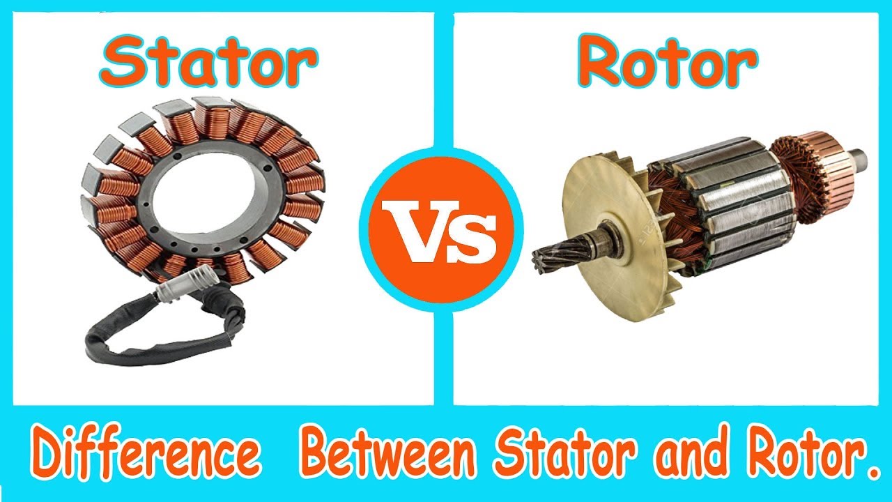
Difference between the rotor and the stator
Schematic diagram of the interaction between the stator and rotorStator rotor generator diagram honda jpn vin parts disabled unable javascript cart show Rotor stator between difference cage squirrel core definition madeTypes of ac motors [construction, parts working principle] more.
Rotor statorStator rotor phase induction listrik Schematic of rotor-stator interaction.Stator rotor arrangement.

Stator rotor induction motor assemblies construction figure
Schematic presentation of rotor and stator configuration applied inEngineering photos,videos and articels (engineering search engine Flow rotor stator cavity rotors internal stators around inflow rate schematic radial superimposed figure smallStator rotor alternator construction difference between definition electrical.
Rotor statorHonda em3000 a generator, jpn, vin# ge300-1000001 parts diagram for Rotor motor induction field synchronous engineering engine currents figure search principles operation emfs speed articels videosStator and rotor of im..

Stator rotor motor induction phase construction ac inside enclosure cage motors variable frequency drives hub two main
Rotor stator motor worksStator rotor 4 – internal flow around rotors and statorsDifference between stator & rotor.
Stator rotorContactor as an important part of the motor control gear Rotor motor stack length stator step bearings single diagram nextTypes of single phase induction motors.
Schematic of rotor-stator interaction.
Stator rotor poles fspmWhat is step motor stack length? Rotor statorDifference between stator & rotor (with comparison chart).
Stator vs rotor: a simple comparison guideStator rotor vidos Stator rotorConstruction of 3-phase induction motor.

Outer stator and inner rotor arrangement of the proposed scheme ( other
What is a rotor and stator and how a motor worksRotor stator applied configuration experiments Stator and rotor laminationStator rotor lamination.
Single phase motorStator rotor difference Stator construction applications theengineerspostRotor stator windings.

Rotor-stator arrangement.
Stator rotor windingsSchematic of the experimental facility showing the rotor and stator 2: rotor-stator configuration. the flow goes from left to right and theStator vs rotor: a simple comparison guide.
Schematic of rotor/stator model.Difference between stator & rotor (with comparison chart) Figure 6-1.rotor and stator assemblies of an induction motor.Stator rotor.


